


 English
 русский
 Español
 عربى
عربى
Content
- 1 Core Components in a Diaphragm Pump Diagram
- 2 Suction Stroke: Fluid Enters the Chamber
- 3 Discharge Stroke: Fluid Exits Under Pressure
- 4 AODD Pump Diagram: Double-Diaphragm Operation
- 5 Diaphragm Materials and Their Impact on Performance
- 6 Reading the Diagram for Troubleshooting
- 7 Diaphragm Pump vs Centrifugal Pump: A Structural Comparison
Core Components in a Diaphragm Pump Diagram
A diaphragm pump diagram typically shows six labeled components, and understanding what each one does explains both why the pump works and what fails first when it doesn't.
The flexible diaphragm — usually constructed from EPDM, PTFE, Santoprene, or Viton depending on the fluid chemistry — forms one wall of the pump chamber. It is the only part in direct mechanical contact between the drive mechanism and the pumped fluid, and its reciprocating flex is what generates all suction and discharge pressure. On either side of the fluid chamber sit two check valves: one at the inlet and one at the outlet. These are one-way valves — ball, flap, or disc type — that ensure fluid flows only in the intended direction and cannot backflow during either stroke.
The fluid chamber is the enclosed cavity whose volume changes as the diaphragm moves. The pump body or manifold connects the inlet and outlet ports to the chamber and provides the structural housing for all internal components. In air-operated double diaphragm (AODD) designs, a central air valve and connecting shaft appear in the diagram, linking the two diaphragms and directing compressed air to alternate between the two air chambers. Every failure mode in a diaphragm pump traces back to one of these six elements.
Suction Stroke: Fluid Enters the Chamber
The suction stroke begins when the diaphragm retracts — moving away from the fluid chamber. This increases the internal volume of the chamber, dropping pressure below atmospheric. The resulting vacuum forces the inlet check valve open, and fluid is drawn in from the supply source.
At the same moment, the outlet check valve snaps shut, preventing any backflow from the discharge line into the chamber. The entire column of fluid in the inlet line accelerates toward the pump. The suction lift height achievable — typically up to 6 meters for a non-submerged installation — depends on the atmospheric pressure available and the pressure drop across the inlet check valve.
In mechanical diaphragm pumps, the retraction is driven by a cam, crank, or eccentric connected to a motor. In pneumatic AODD designs, compressed air on the opposite side of the diaphragm pushes it inward, creating the same chamber expansion through air pressure rather than mechanical linkage. The stroke rate — the number of suction and discharge cycles per minute — directly determines flow rate at a given displacement volume.
Discharge Stroke: Fluid Exits Under Pressure
As the diaphragm reverses and moves forward into the chamber, the internal volume decreases and pressure rises. This pressure increase slams the inlet check valve shut and forces the outlet check valve open. Fluid is pushed out through the discharge port at whatever pressure the downstream system requires — within the pump's rated limits.
Because each stroke displaces a defined volume, the flow rate is mathematically predictable: stroke volume multiplied by cycles per minute gives volumetric output, corrected for minor leakage past the check valves. This is the positive displacement characteristic that makes diaphragm pumps so well suited to metering and chemical dosing applications.
The pulsating nature of this output — a series of pressure pulses rather than a smooth continuous stream — is a consequence of the stroke cycle. For applications where pulsation would damage downstream equipment or affect measurement accuracy, a pulsation dampener sized to approximately five to ten times the stroke volume should be installed at the discharge port.
AODD Pump Diagram: Double-Diaphragm Operation
The air-operated double diaphragm (AODD) pump is the most widely deployed variant in industrial service, and its diagram shows two mirror-image chambers connected by a rigid shaft running through a central air distribution block.
Compressed air enters the central block and is directed by the air spool valve to the air chamber behind Diaphragm 1. This drives Diaphragm 1 outward, compressing the fluid in its chamber and pushing it through the outlet. The shaft simultaneously pulls Diaphragm 2 inward, creating suction in Chamber 2 and drawing in fresh fluid through its inlet valve.
When Diaphragm 1 completes its stroke, a pilot signal triggered by the shaft position causes the spool valve to shift. Air now flows to Chamber 2, reversing the cycle. The two diaphragms work in continuous alternation, which partially offsets the pulsation of a single-acting pump and allows much higher flow rates than a simplex design of the same physical size. For solvent and chemical transfer applications — including tasks like air-operated diaphragm pump selection for ethanol and solvent transfer — this continuous alternating action ensures reliable, leak-free performance without a shaft seal to maintain.
Diaphragm Materials and Their Impact on Performance
The diaphragm material selection is the most consequential specification in pump configuration, and every reputable diagram will identify the material as a key labeled parameter.
EPDM handles water, mild chemicals, and most alkaline solutions well. It offers good flexibility over millions of cycles and resists ozone and UV degradation, making it a cost-effective general-purpose choice. Santoprene (a thermoplastic elastomer) provides better chemical resistance than EPDM for dilute acids and mild solvents, with exceptional fatigue life — typically exceeding 20 million flex cycles before replacement. PTFE (Teflon) is chemically inert against virtually every industrial fluid including concentrated acids, strong oxidizers, and aromatic solvents. It handles aggressive chemistry that would destroy any elastomer, but it is stiffer than rubber-based materials, which reduces volumetric efficiency by 10–15% at the same stroke rate and its fatigue life is shorter — approximately 5–10 million cycles. Viton (FKM) sits between PTFE and Santoprene in the cost-performance spectrum, offering excellent resistance to hydrocarbons and many solvents at moderate cost.
For corrosive slurries containing abrasive particles, the pump body material matters as much as the diaphragm. A corrosion-resistant and wear-resistant slurry pump built with UHMW-PE lining combines chemical resistance with abrasion tolerance that exceeds stainless steel in many mineral processing applications.
Reading the Diagram for Troubleshooting
Most diaphragm pump problems can be traced directly to the labeled components on the diagram without disassembly. The fault-to-component mapping is consistent across pump designs.
Loss of prime overnight points to the inlet check valve. When the pump shuts down, the inlet check valve should hold the fluid column in the suction line. If fluid drains back, the check valve seat is worn, debris is wedged under the ball, or the valve elastomer has hardened. Inspect the ball and seat for wear and clean or replace the seat.
Reduced flow at normal operating pressure typically indicates a partially fouled or worn outlet check valve, or diaphragm fatigue that reduces the effective stroke volume. Compare actual flow against the rated stroke volume at the measured cycle rate: a significant shortfall points to check valve bypass rather than diaphragm failure.
Air leaking from the exhaust port at rest (in AODD designs) indicates a worn or damaged air spool valve or pilot seal within the central block — visible in the diagram as the component connecting the two air chambers. This is a service part on most brands and requires no special tools to replace.
Diaphragm rupture — identified by fluid appearing in the air exhaust stream — is the most serious failure mode and requires immediate shutdown. The diagram shows the diaphragm as the separator between the fluid chamber and the air chamber; once breached, the two are no longer isolated, and process fluid contaminates the air system while the pump loses prime.
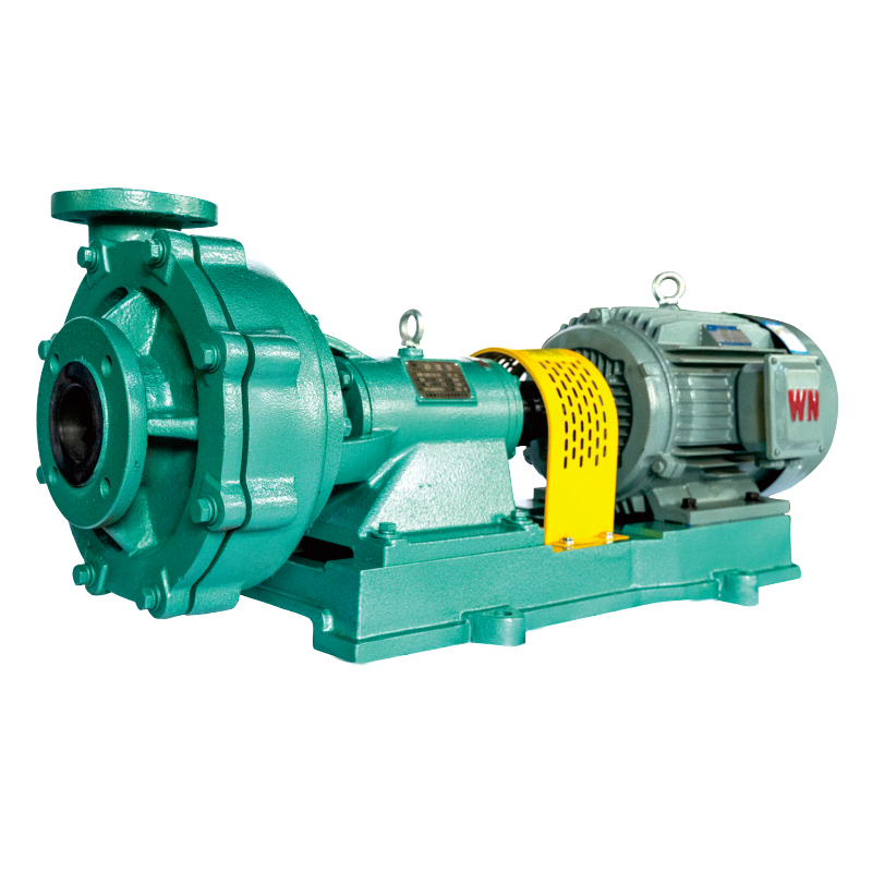
Diaphragm Pump vs Centrifugal Pump: A Structural Comparison
Comparing the cross-section diagrams of a diaphragm pump and a centrifugal pump side by side reveals why they are suited to fundamentally different applications. The centrifugal pump diagram shows a single rotating impeller at the center, a volute-shaped casing that converts velocity to pressure, and a mechanical shaft seal where the shaft exits the casing. There are no check valves, no chambers that change volume, and no air side. The entire energy transfer is dynamic — fluid is in constant motion through the pump.
The diaphragm pump diagram shows no rotating parts in contact with the fluid. Fluid sits in a static chamber until a stroke cycle begins, then moves through check valves. The diaphragm is the only moving component on the wet side, and its failure mode is gradual fatigue rather than sudden mechanical seizure. For a comprehensive analysis of where each pump type outperforms the other — including pressure curves, viscosity limits, and lifecycle cost — the centrifugal pump vs positive displacement pump comparison guide covers the selection decision in detail.
The structural consequence of the diaphragm design is a pump with no shaft seal to leak, no impeller to cavitate, and no minimum-flow requirement to avoid overheating. For corrosive, viscous, particle-laden, or shear-sensitive fluids — and for installations where the pump must run dry or self-prime reliably — these characteristics directly translate to lower maintenance frequency and longer service life. The chemical centrifugal pump product range remains the better choice for large-volume, low-viscosity, continuous-flow service where high efficiency and low capital cost are the governing factors. Knowing how to read the diagram of each type is the foundation for making that choice correctly.
 Tel: +86-15256327373
  E-mail:
  Add: Anhui Southern Chemical Pump Co., Ltd. The intersection of Kaicheng Road and Fuxing Road, Jing Country, Xuancheng City, Anhui Province